JVC KM-F250

1×S-Video (Y/C) (Hirose 7-pin DUB)
1×Y/C DUB color-under (Hirose 7-pin DUB)
1×Component (YPbPr) (BNC)
1×RF (BNC)
1×Composite (CVBS) (BNC)
2×Composite (CVBS) (BNC)
1×Composite (CVBS) (BNC)
1×Y/C DUB color-under (Hirose 7-pin DUB)
1×Composite (CVBS) (BNC)
1×Composite (CVBS) (BNC)
1×S-Video (Y/C) (Hirose 7-pin DUB)
1×Composite (CVBS) (BNC)
1×Component (YPbPr) (BNC)
Description
The JVC KM-F250 is a professional rack-mountable frame synchronizer with integrated full-frame time base correction, originally marketed by JVC's Professional Products division. Though officially designated a "frame synchronizer," the unit performs full-frame TBC processing conforming to CCIR Recommendation 601 at 13.5 MHz, 8-bit 4:2:2 sampling, effectively making it a multi-purpose TBC suitable for professional video production and archival workflows.
The KM-F250 accepts composite (VBS), Y/C separate, and analog component (Y/R-Y/B-Y) video inputs. A loopthrough reference sync (black burst/genlock) input is provided for synchronizing output timing to external equipment, along with a dedicated DOC (dropout compensator) RF carrier input for use with VTRs that provide an RF output. The unit provides two composite video outputs, component outputs, Y/C separate outputs, and four sync reference outputs (ADV SYNC for VTR servo lock, REF SYNC composite sync, REF SC color subcarrier, and REF BB black burst).
The unit includes comprehensive proc amp controls behind the front panel: video (Y) level, chroma level, U-V balance, and setup level — each with a variable/unity switch allowing ±3 dB adjustment (±10% for setup). An H position control allows output horizontal timing adjustment within ±7 µsec, and a Y/C timing control adjusts chroma-to-luminance phase within ±1 µsec. A chroma advance switch advances the chroma output by 1H with respect to luminance when enabled. All front-panel controls can be disabled via a LOCAL/REMOTE switch when using the optional JVC RM-P250 remote control unit.
The unit features field freeze and frame freeze functions, useful for still-frame capture in production environments.
Internally, the KM-F250 comprises ten circuit boards: RL (relay/bypass switching), CN (connector interface), MT (mounting/interconnect), VIDEO (analog signal processing), MEMORY (digital TBC/frame memory with A/D and D/A conversion), SG (sync generator/SSG), PS (switching power supply producing +12V, −12V, and +5V), REG (voltage regulator converting ±12V to ±9V for video circuits), SUB (subsidiary functions), and PB DET (playback detection).[1]
The KM-F250 is relatively obscure compared to competing TBCs from FOR-A, DataVideo, and Snell & Wilcox, but is encountered in both US broadcast facilities and European archival environments.
Variants
The KM-F250 was produced in several regional variants with significant differences in Y/C signal handling and power supply configuration:
- KM-F250U — NTSC variant for the US market (120V, 60Hz). Y/C uses a Hirose 7-pin DUB connector supporting both S-VHS (3.58 MHz) and U-matic DUB (688 kHz) modes, selectable via internal switches behind the front panel.[2][3]
- KM-F250E — European PAL variant (100–240V, 50/60Hz). Y/C uses a 7-pin DIN connector (with included 7P-to-BNC adapter cable). Supports Y/C 443 at 4.43 MHz (PAL S-VHS), Y/C 924 at 924 kHz (hi-band U-VCR), and Y/C 629 at 629 kHz (VHS). Output Y/C format is selectable via a rear-panel switch (443/924/629), while input Y/C format is set via an internal select pin.[1]
- KM-F250EG — European PAL variant (230V, 50Hz)
The European variants accept PAL input and can output NTSC 4.43 (pseudo-NTSC with PAL subcarrier frequency), functioning as a basic standards transcoder. The unit was designed for use with consumer and semi-professional video systems including S-VHS, VHS, U-matic, and other formats.
-
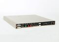 JVC KM-F250E front panel (European PAL variant)
 -
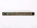 JVC KM-F250E rear panel (European PAL variant)


Photos


Signal Specifications
The following input/output specifications are derived from the JVC KM-F250 user manual (NTSC model)[4] and the KM-F250E service manual (PAL model).[1]
Input Signals
| Signal | NTSC Model (U) | PAL Model (E/EG) | Impedance |
|---|---|---|---|
| Composite (VBS) | 1.0 Vp-p | 1.0 Vp-p | 75 Ω |
| Y (luminance) | 1.0 Vp-p (with sync) | 0.7V + 0.3V sync (Y/C 443) or 0.35V + 0.15V sync (Y/C 924/629) | 75 Ω |
| C (S-VHS, 3.58 MHz) | 0.286 Vp-p (burst) | 4.43 MHz, 0.3 Vp-p (burst) | 75 Ω |
| C (U-VCR, 688 kHz) | 0.50 Vp-p | 924 kHz, 1.0 Vp-p (VBS) | 75 Ω |
| C (VHS) | — | 629 kHz, 1.0 Vp-p (VBS) | 75 Ω |
| Component Y | 0.7V + 0.3V sync | 0.7V + 0.3V sync | 75 Ω |
| Component R-Y | 0.7 Vp-p (100%) / 0.486 Vp-p (75%) | 0.7 Vp-p (100%) / 0.486 Vp-p (75%) | 75 Ω |
| Component B-Y | 0.7 Vp-p (100%) / 0.486 Vp-p (75%) | 0.7 Vp-p (100%) / 0.486 Vp-p (75%) | 75 Ω |
| Reference sync | Black burst 0.45 Vp-p or composite 1.0 Vp-p | Black burst 0.45 Vp-p or PAL-B composite 1.0 Vp-p | 75 Ω (loopthrough) |
| DOC RF carrier | 0.2–1.0 Vp-p (3–10 MHz) | 0.2–1.0 Vp-p (3–10 MHz) | 75 Ω |
Output Signals
| Signal | NTSC Model (U) | PAL Model (E/EG) | Impedance |
|---|---|---|---|
| Composite (VBS) × 2 | 1.0 Vp-p | 1.0 Vp-p | 75 Ω |
| Y (luminance) | 1.0 Vp-p (with sync) | 0.7V + 0.3V sync (443) or 0.35V + 0.15V sync (924/629) | 75 Ω |
| C (S-VHS, 3.58 MHz) | 0.286 Vp-p (burst) | 4.43 MHz, 0.3 Vp-p (burst) | 75 Ω |
| C (U-VCR, 688 kHz) | 0.85 Vp-p | 924 kHz, 0.5 Vp-p | NTSC: 390 Ω / PAL: 75 Ω |
| C (VHS) | — | 629 kHz, 0.5 Vp-p | 75 Ω |
| Component Y | 1.0 Vp-p (with sync) | 0.7V + 0.3V sync | 75 Ω |
| Component R-Y/B-Y | 0.7 Vp-p (100%) / 0.486 Vp-p (75%) | 0.7 Vp-p (100%) / 0.486 Vp-p (75%) | 75 Ω |
| ADV SYNC | 4 Vp-p (advanced 8H) | 4 Vp-p (advanced 8H) | 75 Ω |
| REF SYNC | 4 Vp-p | 4 Vp-p | 75 Ω |
| REF SC | 1 Vp-p | 1 Vp-p | 75 Ω |
| REF BB | 0.45 Vp-p | 0.45 Vp-p | 75 Ω |
Note: On NTSC models (KM-F250U), Y/C input and output use a single Hirose 7-pin DUB connector supporting both S-VHS (3.58 MHz) and U-matic DUB (688 kHz) modes. The Y/C INPUT and Y/C OUTPUT switches behind the front panel select between S-VHS and U-VCR modes. On PAL models (E/EG), Y/C input and output use a 7-pin DIN connector with an included 7P-to-BNC adapter cable; the input format is set via an internal select pin (Y/C 443, Y/C 924, or Y/C 629), while the output format is selectable via the Y/C OUTPUT switch.
Performance Specifications
The following performance measurements are from the KM-F250U user manual[4] and KM-F250E service manual.[1]
| Parameter | Composite | Component | Y/C Separate |
|---|---|---|---|
| S/N ratio | 58 dB or more | ||
| Residual jitter | ±15 nsec | ±15 nsec | Luminance ±15 nsec, hue ±2° |
| K Factor (2T Pulse) | 3% | 1% | 1% |
| Frequency response | 4 MHz, ±0.5 dB | Y: 5.5 MHz, ±0.5 dB; R-Y/B-Y: 2.5 MHz, ±0.5 dB | Y: 5.5 MHz, ±0.5 dB; C: 500 kHz, −3 dB |
Ambient operating temperature: 5 to 40°C (41 to 104°F).
Known Issues
The most commonly reported failure mode is loss of video output when the unit is switched from bypass to operate mode. The front-panel "low video level" indicator illuminates and the output goes to black, while bypass mode passes video normally. Forum discussions indicate this is typically caused by power supply degradation.[5]
The PS (power supply) circuit board uses a switching regulator to produce +12V, −12V, and +5V DC rails. The REG (regulator) board then converts the ±12V rails to ±9V for the video processing circuits. Failure of any rail can prevent the digital processing circuitry from functioning while bypass mode (which routes signals through the RL board's analog switching circuit) continues to pass video normally.[1]
The user manual (page 9) describes a video level adjustment trimmer, but users report this trimmer has no effect when the underlying issue is a power supply fault.[5]
See Also
- JVC RM-P250 — Optional wired remote control unit
- Frame synchronizers
- Time base correctors and frame synchronizers
References
- ↑ 1.0 1.1 1.2 1.3 1.4 Document:JVC KM-F250E Service Manual — JVC service manual No. 6455 for the KM-F250E. Contains circuit descriptions, adjustment procedures, exploded views, parts lists, and schematic diagrams.
- ↑ BroadcastStore.com — "JVC KM-F250U TBC &/or Frame Synchronizer" — US broadcast equipment dealer listing confirming KM-F250U model designation.
- ↑ Reddit r/VIDEOENGINEERING — "My JVC KM-F250 Frame Synchronizer/Time Base Corrector" — Owner photos of a KM-F250U unit showing front panel, rear I/O, and internal components.
- ↑ 4.0 4.1 JVC KM-F250 User Manual (English) — hosted by Adcom S.r.l. Original manufacturer documentation covering signal specifications, operating procedures, and adjustment trimmers.
- ↑ 5.0 5.1 VideoHelp Forum — "JVC KM-F250 TBC no output" — Multiple users report identical symptoms (black output with "low video level" indicator in operate mode). Power supply voltage rail failure identified as likely cause.
